Drift tracks for the HPI Stage-D24 (161267 & 161268)
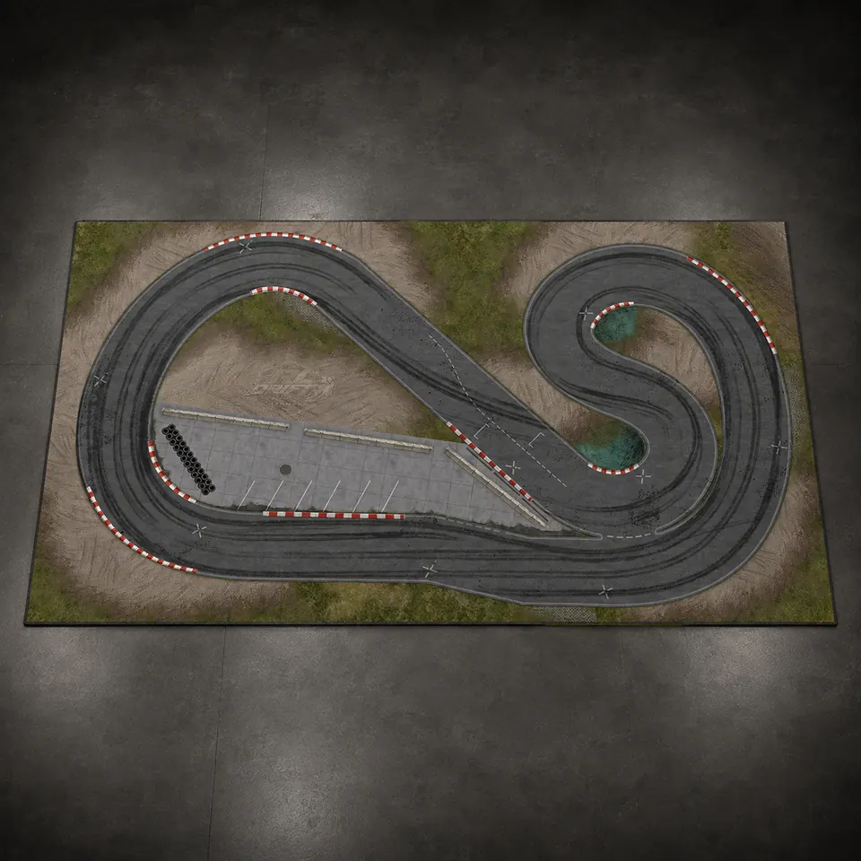
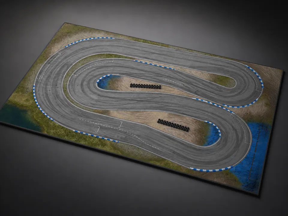
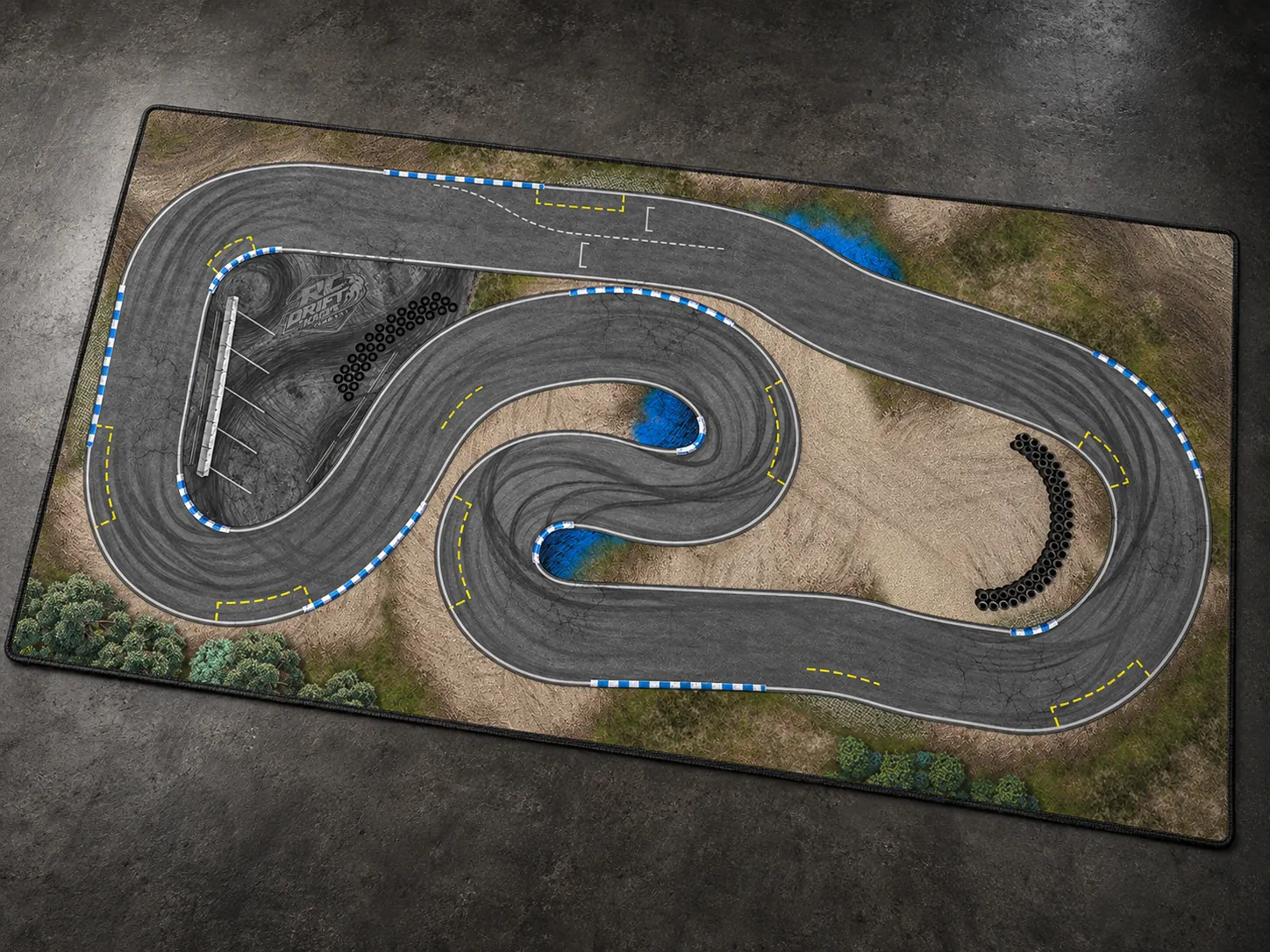
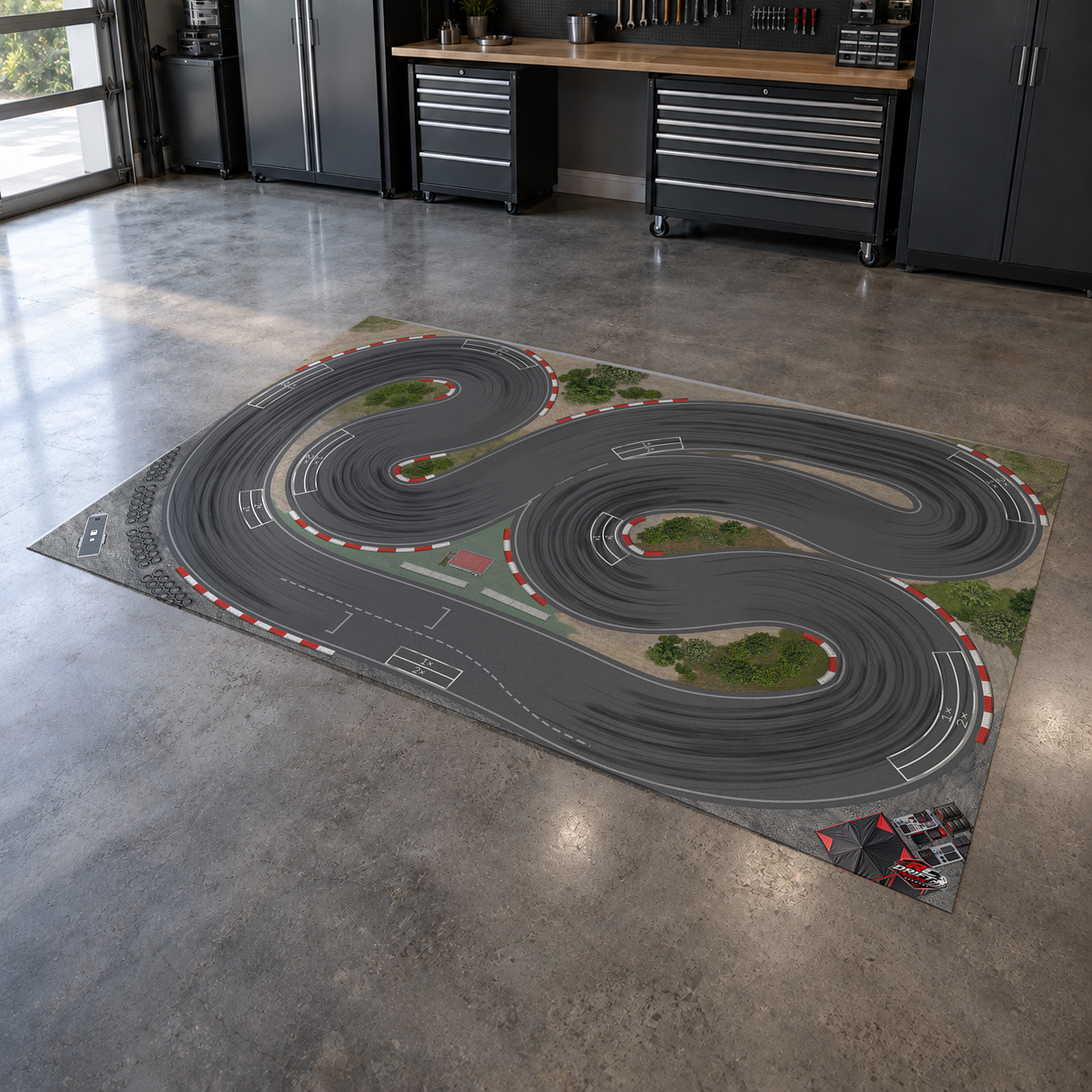
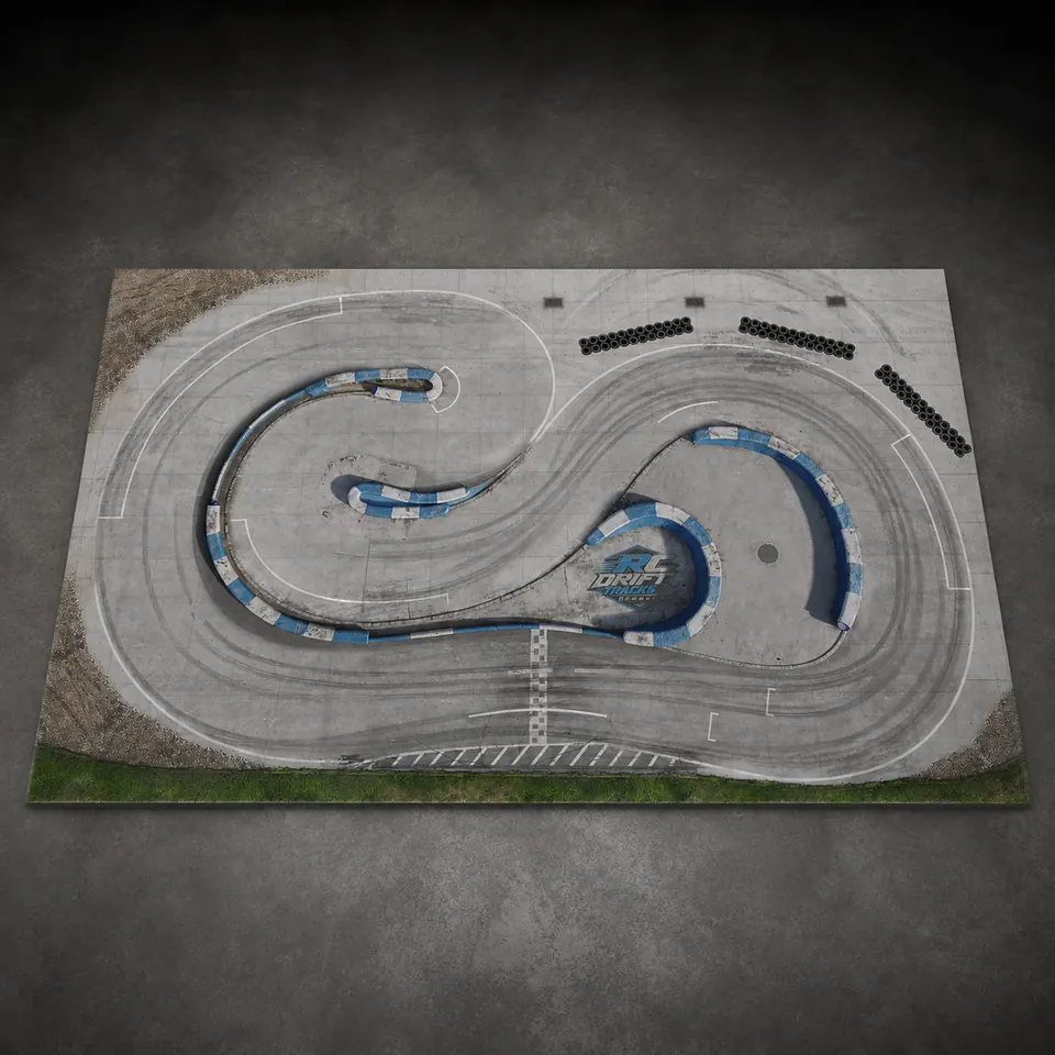
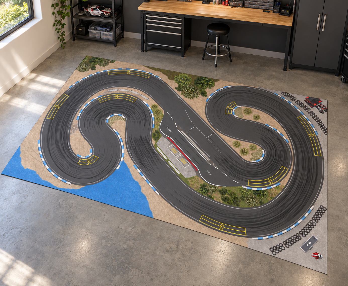
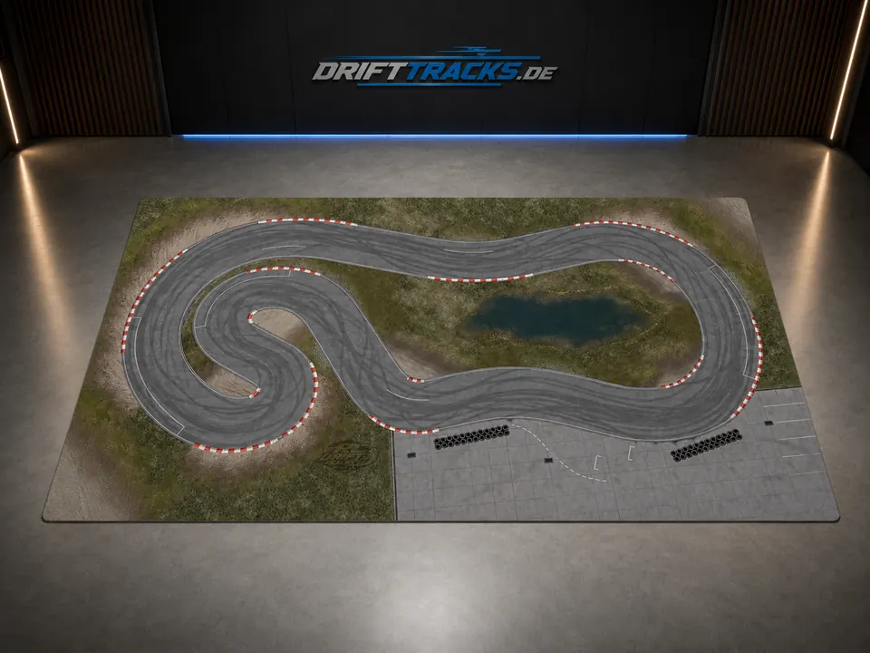
The HPI Stage-D24 brings true RWD drifting to 1:24 scale. A defined track turns a few laps on the floor into repeatable lines, transitions and countersteer. Our roll-out 1:24 PVC drift tracks transform a living room, hobby room, basement or garage into a complete RC drift circuit with realistic layouts, curbs and track detail.
A well-tuned setup lays the groundwork. Smooth, controlled drifts come from practice, carefully measured throttle and your own counter-steering inputs.
Our practical settings on DriftTracks mats are starting points, not HPI factory specifications or guaranteed ideal values. Check free movement first, then ride height and geometry.
01Fit lower-grip tyresChoose suitable drift tyres; check dimensions and wheel fit before ordering.
The stock tyres have too much grip for the slow drift we want on our mat. Suitable lower-grip drift tyres from other micro-drift models or manufacturers can make drifts slower and more controlled, with a more realistic look. Check dimensions and wheel fit before ordering.
Tyres first, geometry next
Tyres are the foundation for the remaining setup. Changing wheels can affect not only grip and driving feel, but also ground clearance and chassis attitude.
Your check
Check ride height with the battery and body fitted on a level surface before readjusting camber and toe.
02Check that the front wheels spin freelyCheck that both front wheels spin freely straight ahead and when steering.
Both front wheels must spin as freely and easily as possible – straight ahead and across the full steering sweep to the left and right. They must never bind, catch or rub when you steer. Check them again after changes to track width, camber or steering. This concerns the free rotation of the wheels themselves, not just the movement of the steering servo.
Free movement in every check position
A wheel can spin freely when straight yet still rub during counter-steering. Clearance therefore needs to remain throughout the steering range you use and at different suspension positions.
Your check
Check both front wheels individually: straight ahead, at typical counter-steering angles and at maximum lock.
03Make the front suspension move smoothlyLightly lubricate sliding points with a suitable dry lubricant.
Lightly lubricate the moving sliding points of the front suspension with a suitable, plastic-compatible dry lubricant so the suspension responds softly and evenly. We use dry lubricant so less dust and hair sticks to the sliding points and interferes with the suspension. Keep the tyres and the driving surface clean while doing so.
Check free suspension movement before setting ride height. Do not conceal binding with extra spring preload.
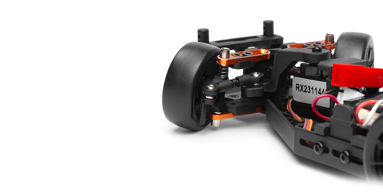
Check suspension and linkage separately
This view shows the front suspension and steering mounting points. The linkage point affects the relationship between steering angles; free compression and extension remain a separate, equally important check.
Your check
After a change, check joint movement, screw engagement and wheel clearance. This image is not a universal installation plan.
Free movement, not concealed binding
Dry lubricant can be part of front suspension maintenance. It does not replace checking for stressed, incorrectly seated or binding components.
Your check
The suspension must move without catching and settle consistently; do not conceal binding with additional preload.
04After changing tyres: check ride height and chassis attitudeSmaller wheels reduce ground clearance. Check front and rear height, adjust spring preload if needed and check the lowest suspension parts for rubbing.
1. Check height and chassis attitude
When changing to other drift tyres and wheels, the outside diameter may be smaller than the HPI stock tyres. Wheel-and-tyre combinations around 22 or 22.5 mm outside diameter are one example. What matters is the actual diameter of the assembled wheel, not just the rim specification.
Smaller wheels bring the car closer to the ground. Check both clearance and the chassis attitude between the front and rear axles. If the front sits too low after the change, readjust the height. However, making all four wheels equally smaller does not necessarily create a new tilt. Measure and check first rather than automatically raising the front.
Front too low
This side view shows the low front of our HPI. Smaller complete wheels can reduce ground clearance, so check chassis attitude between the front and rear axles after a wheel change.
Your check
Do not raise the front automatically. First check the ready-to-drive car on a level surface; weight distribution cannot be inferred from this photo.
Height corrected
This image provides a comparison for corrected chassis attitude, not a universal ride-height measurement. The final setting depends on your wheels and your ready-to-drive car.
Your check
Check with the battery and body fitted: sufficient ground clearance, remaining droop travel and free movement during compression and steering.
2. Adjust spring preload in small steps
On our HPI build, suitable spacers at the upper spring seat can increase preload and raise the front, provided downtravel remains available. Dimensionally accurate 3D-printed rings or suitable burr-free washers from model suppliers or hardware shops are options. They must sit properly and must not obstruct the spring guide.
Use preload deliberately
The tool points to the upper spring seat. Spacers placed here can change preload and ride height while droop travel remains; they do not increase the spring rate itself.
Your check
Work in small, equal steps on both sides. Do not stack spacers up to the droop stop or use them to conceal binding suspension.
Start with equal spacer thickness on both sides and make small changes. After each adjustment, place the ready-to-drive car on a flat surface, gently compress the front suspension and release it. It must move freely and repeatedly return to a comparable resting position. Include the battery and body in the final height check.
How to check ride height and spring movement
The clip shows the front suspension compressing and returning, first in real time and then in slow motion. Look for free movement without catching and a repeatable resting position after release.
Original silent clip with German on-screen labels. The included slow-motion section runs at 0.65× speed. It demonstrates spring movement, not a measured damping curve or oil damping.
3. Main chassis plate: prevent grounding
If you run complete wheels measuring 22 or 22.5 mm after changing tyres, keep an eye on the main chassis plate as well, not just the lower front suspension bush. With little ground clearance, the plate can ground on uneven surfaces or a PVC mat with slight waves. This slows the car abruptly and interrupts a steady drift, making the driving look unsettled rather than clean and smooth.
Lower is not always better
Your photo shows the low main chassis plate from the side. With 22 or 22.5 mm complete wheels, the remaining clearance can be insufficient on uneven ground or small PVC waves. Plate contact slows the drift abruptly.
Your check
Check ready to drive and test slowly on your surface. The photo compares chassis positions; it does not provide a measurable clearance value.
More clearance for a steady drift
The second side view shows the higher main chassis plate position. If your chassis grounds, our 0.5 mm washer beneath the T-bar is a starting point for adjustment, not an automatic modification for every car.
Your check
After adjustment, check chassis attitude, free suspension movement and clearance with the battery and body fitted, then drive a slow comparison lap.
If the main chassis plate grounds, our recommended starting point is a 0.5 mm washer used as a spacer under the T-bar. This is our practical tip, not an HPI factory specification.
Start with 0.5 mm beneath the T-bar
The tool indicates the T-bar mounting area from below. This locates our chassis-height spacer tip. A suitable burr-free washer beneath the T-bar is our recommendation if the main chassis plate grounds on your driving surface.
Your check
Disconnect the battery, check seating and screw engagement, and avoid stressing the T-bar. Afterwards check for contact ready to drive, during compression and while steering.
Do not add the spacer automatically: use it only when clearance is genuinely insufficient. Disconnect the battery before working. The washer must fit the mounting surface, be burr-free and sit properly beneath the T-bar; afterwards check screw engagement and free suspension movement. With the battery and body fitted, recheck front-to-rear chassis attitude and clearance during gentle compression and steering. Test slowly on your actual driving surface to confirm the plate stays clear. Flatten waves in the mat wherever possible: extra height is not a substitute for a level surface.
02Steering & geometry
05Allow more usable steering angleClip the knuckle stops; afterwards, always adjust steering EPA endpoints so the wheels cannot fold over.
Our tip for more usable steering lock: clip the steering stops on the knuckle with suitable pliers. First identify exactly which small stops limit steering travel. Disconnect the battery, remove the affected parts if needed and clip only the clearly identified stops, leaving joint mounts and load-bearing areas untouched. This is an optional, irreversible modification for experienced builders.
Essential afterwards: adjust EPA (End Point Adjustment), the steering endpoints on your transmitter, separately for left and right. Start with limited travel and increase it only as far as the wheels cannot fold over and the linkage stays within its usable range. Check both directions during compression too: nothing must bind, rub or make the servo push against resistance. Then also check the gyro’s counter-steering movement.
Use steering lock without contact
More steering lock only helps when the wheels remain free to move. Check both sides: free movement in one direction does not establish clearance in the other.
Your check
Steer slowly to both limits and also check during compression whether tyres or rims touch any components.
06Set the front axle widerSet the front slightly wider than the rear; keep the wheels clear when steering.
Set the front track slightly wider than the rear and make equal changes on both sides. On our setup, this gives the front axle more guidance: the car can be easier to guide calmly through a drift, with smoother transitions. The wheels must remain clear throughout the steering range.
On our build, a wider rear track tends towards more rear grip. Front-axle guidance then becomes less dominant and the drift can feel more abrupt rather than clean and smooth. That is not the balance we want here. This is our setup tendency, not a guaranteed effect for every tyre and surface combination. Test small changes individually and then recheck toe and clearance.
Match track width to clearance
Track width is part of your front axle's overall geometry. Changing it alters the space around the wheels and needs to be assessed together with steering lock and tyre contact.
Your check
Make equal changes on both sides, then check both wheels for free movement during counter-steering and suspension travel.
07Camber and caster: tune tyre contact in the driftOur starting point is around −6° to −7° front camber. Less can also work. Check tyre contact during counter-steering and always prioritise free suspension movement over a specific number.
Our starting point: −6° to −7°
For our HPI Stage-D24, we use about 6–7° negative front camber as a starting point. Negative camber means the tops of the wheels lean inward. Measure initially with the steering straight and the car at ready-to-drive ride height.
Look beyond the camber angle
The front view helps you compare the inclination of both front wheels. For your drift, it also matters how tyre contact changes at the steering angles you actually use.
Your check
Readjust toe and Ackermann after every camber change, then check suspension movement and counter-steering. Free movement still matters more than a particular angle.
This value is not mandatory. Less negative camber can also work well, depending on tyres, surface, steering angle and your driving style. On our setup, more negative camber can feel more agile at the initial steering input. This is a tuning tendency, not a general promise that more camber always brings more steering or grip.
Distinguish camber from caster
Static camber describes wheel inclination with straight steering, but does not by itself describe the wheel position during a turn. Caster is the steering-axis inclination viewed from the side. Caster and steering geometry influence how wheel inclination changes while steering.
Check tyre contact during counter-steering
This angled view shows why a straight-ahead check alone is insufficient. Camber and caster affect tyre contact during steering in different ways; adding camber does not replace every effect of changing caster.
Your check
Optimise the leading tyre’s contact at your most-used drift steering angle, check both sides and readjust toe/Ackermann after camber changes. This HPI assembly has no separate stock caster adjustment.
The HPI build shown here does not give us a separate stock caster adjustment. We therefore use camber to tune tyre contact at the counter-steering angles we actually drive. This does not replace all the effects of a caster change.
With the existing caster, tune camber so the leading front tyre has the best possible contact patch at the steering angle you use most often in a drift. Check the equivalent situation in both drift directions: the main working angle matters more than perfect contact only with straight steering.
After every camber change, recheck and readjust toe and the Ackermann progression. The new wheel inclination changes the geometry, so do not simply retain the previous steering setup without checking it.
Check both front wheels during counter-steering
Look at both front wheels: not only the more heavily loaded wheel in the corner, but also the front wheel leading in the drift. The actual drift motion and counter-steering matter. Do not automatically equate the leading wheel with the inside wheel according to steering direction.
Check contact with straight steering, typical counter-steering angles and maximum usable lock, in both directions. Do not force both tyres to have full contact at every angle. What matters is a controllable combination of tyre contact, freely spinning wheels and smooth suspension.
08Tune static toe and Ackermann separatelyStart neutral to slightly toe-out. Keep the wheels near-parallel through steering, opening slightly at the end; urgently avoid toe-in while steering.
Static toe: with straight steering
Static toe describes wheel alignment at a specified ride height with the steering straight. With toe-out, the front edges point apart; with toe-in, they point towards each other. For our HPI baseline, start with neutral to slight front toe-out.
Ackermann: while steering
Ackermann describes the relationship between the steering angles of the two front wheels during steering. For our HPI drift setup, aim for near-parallel wheels throughout the usable steering range, opening slightly towards toe-out at the end. Slight toe-out elsewhere in the sweep is acceptable too. Check the progression in both directions, free wheel rotation and suspension movement, not just one maximum steering angle.
Urgently avoid toe-in while steering: for our setup, the wheels should not close towards each other. Check the full usable steering sweep in both directions and correct the linkage if this occurs.
Measure and compare our toe settings
Compare toe consistently
This overview shows our steering toe setting, not a bumpsteer check. The dimensions belong to our camber and track width; do not copy them to your car without checking. Consistent measuring conditions make the adjustment repeatable.
Your check
Measure equivalent steering points on both sides at the same height and corresponding steering positions so left and right are set identically.
Consistent points, useful measurements
This close-up shows our toe measurement. The reading depends on camber, track width and measuring points. The aim is not to copy our number but to set your steering identically on both sides and compare its progression while steering.
Your check
Repeat measurements on both sides; readjust toe/Ackermann after every camber or track-width change. Compare straight ahead and at corresponding steering angles in both directions.
The two caliper photos show our toe settings, not a bumpsteer measurement. The dimensions depend on our camber and track width and are not universal millimetre targets. Always measure the steering while adjusting it: compare equivalent points on the left and right at the same ride height and corresponding steering positions so both sides are set identically. Check straight ahead and at matching angles to the left and right. Remeasure and readjust toe/Ackermann after changing camber or track width.
Bumpsteer: during suspension travel
Bumpsteer, in contrast, is a change in toe or wheel steering angle caused by suspension compression or extension with the steering input unchanged. Check it separately in the next step.
For this HPI drift baseline, we do not recommend deliberately tuning a toe change towards toe-in on droop.
09Bumpsteer: keep wheel alignment as constant as possible through suspension travelCheck whether toe changes during compression and extension. Our baseline is minimal bumpsteer. A slight increase in toe-out on droop remains an optional fine-tuning experiment.
Baseline: near-constant wheel alignment
When the front wheels open or close during compression or extension despite an unchanged steering input, this is bumpsteer. It can affect the driving feel even though you have not applied more steering on the transmitter.
For our HPI baseline on DriftTracks mats, start with as little bumpsteer as possible: toe or wheel steering angles should change as little as possible within the suspension travel actually used. Check with straight steering first, then at typical counter-steering angles.
Adjust steering-link mounts deliberately
Suitable washers can change the height of the steering-link mounting points and therefore the bumpsteer curve. These spacers serve a different purpose from spring-preload spacers. Check the appropriate position and thickness against the actual geometry.
Identify toe changes during suspension travel
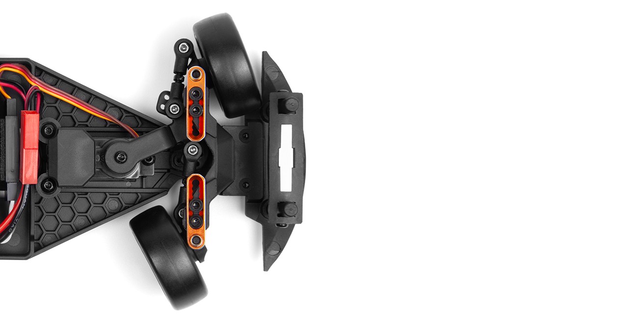
This top view shows a front axle check. Bumpsteer means that toe changes during compression or extension even though your steering input stays the same.
Your check
Move the axle slowly and measure rather than estimating. The photo does not specify spacer thickness or installation position; near-constant wheel alignment remains our starting point.
How to check bumpsteer
Set ride height, camber and static toe first.
Keep steering input constant. Exclude gyro corrections during the check and do not run the drivetrain. Do not push against the servo.
Move the front suspension slowly through the compression and extension range used. Observe both sides and measure where possible rather than guessing.
If wheel alignment changes, adjust the steering-link mounting in small steps and recheck. Start symmetrically on the left and right.
Then recheck static toe, screw engagement, joint movement, wheel clearance and behaviour during counter-steering.
The photo illustrates the check. It is not a measured spacer installation plan or before-and-after proof. It does not establish washer thickness, mounting position or adjustment direction.
03Rear suspension, gyro & throttle
10Adjust the rear suspension carefullyLoosen the T-bar screws only slightly; the mounting must not develop loose play.
For a rear end that responds more softly, you can slightly loosen the screws on the T-bar. Work your way there in small steps. The screws must still grip securely; the mounting must not develop any loose play. This is our practical tip – not a factory specification from HPI.
Include the rear axle
The T-bar is part of the rear axle setup. Assess changes alongside turn-in, maintaining the drift angle and the car's response to measured throttle inputs, rather than in isolation.
Your check
Change only one setting and drive the same line several times before making another adjustment.
11Tune the gyro step by stepIncrease gain until wobble begins, then dial it back a little.
Increase the gain in small steps until the steering shows the first signs of restlessness or wobble. Then dial it back a little until the steering stays calm. Work by feel rather than a blanket percentage – the goal is calm steering without wobble.
12Reduce power and apply throttle gentlyOur starting point: 75% maximum throttle output; apply throttle gently on corner exit.
You do not always need full motor power. Try reducing the throttle output on your transmitter. Our starting point for DriftTracks mats is 75% of maximum throttle output. With our setup, this makes the car easier to catch after a measured throttle blip on corner entry and less likely to spin. On corner exit, apply only a very small amount of throttle gently until traction builds again. Then gradually increase the throttle.
Electronics after mechanics
Gyro and throttle settings let you refine driving feel. They cannot compensate for binding front suspension, rubbing wheels or unsuitable geometry.
Your check
Check the mechanics first, then change one setting at a time and test with carefully measured throttle.
4. Train your driving feel
Now it's about your feel on the controls.
Practise clean lines repeatedly.
Practise your own, well-measured counter-steering inputs. Less gyro can be more.
Apply throttle gently: on corner exit, start with very little until traction builds again.
Test each change separately and check the steering after every adjustment.
Practice makes perfect. With a smooth-running chassis, a suitable setup and a bit of training, you can get closer and closer to the calm, realistic driving look in the videos above.
DriftTracks · Stage-D24
From workbench checks to a clean line.
Which Stage-D24 do you have?
Both versions are the 2024 Toyota GR Supra in 1:24 with rear-wheel drive. The same DriftTracks layouts fit both. We sell tracks and accessories – not HPI cars.
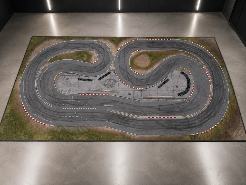
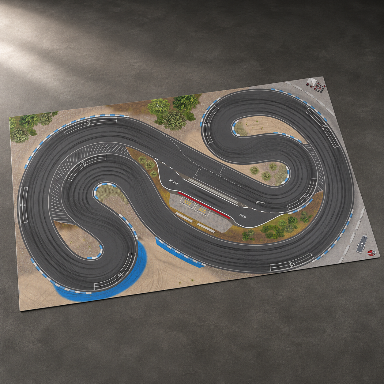
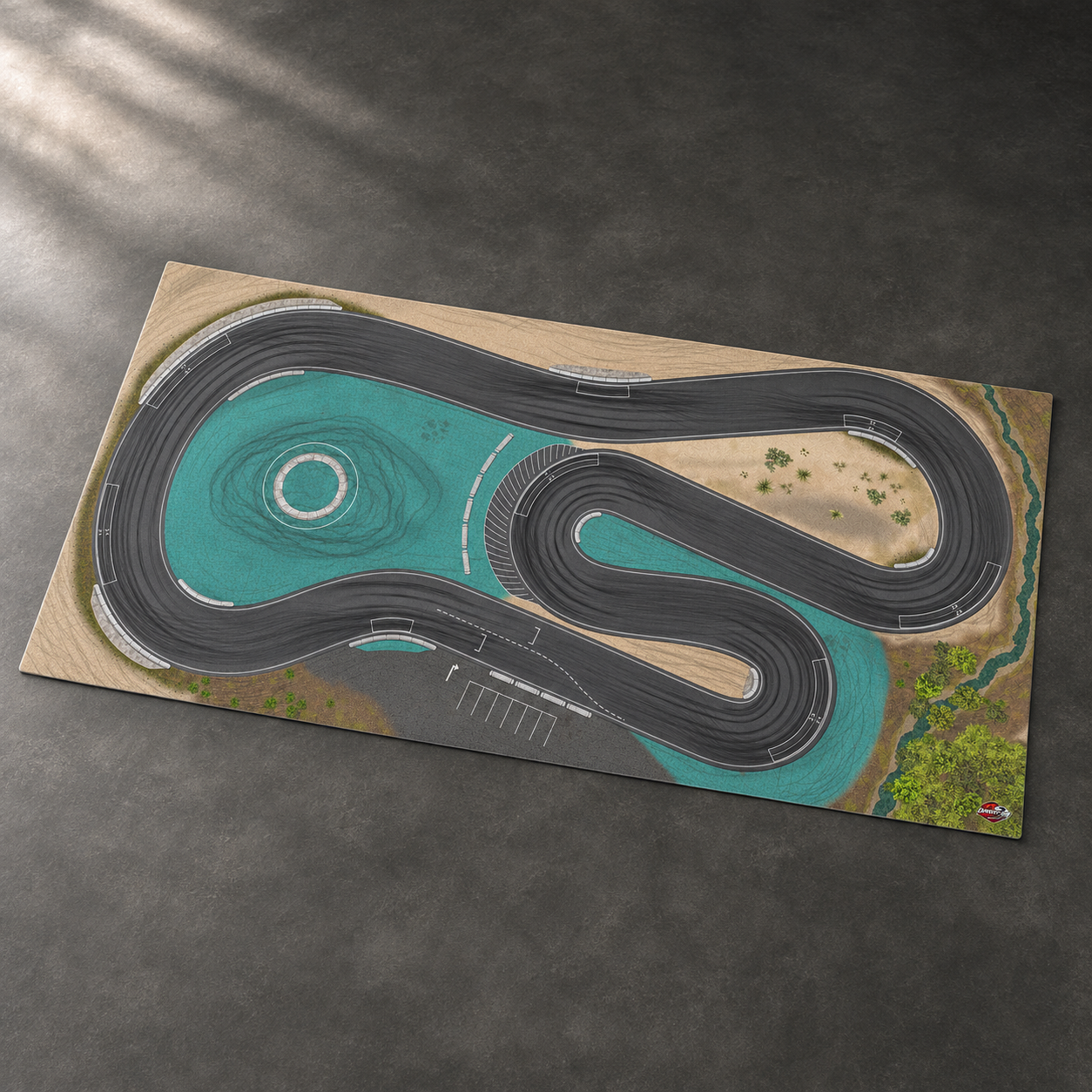
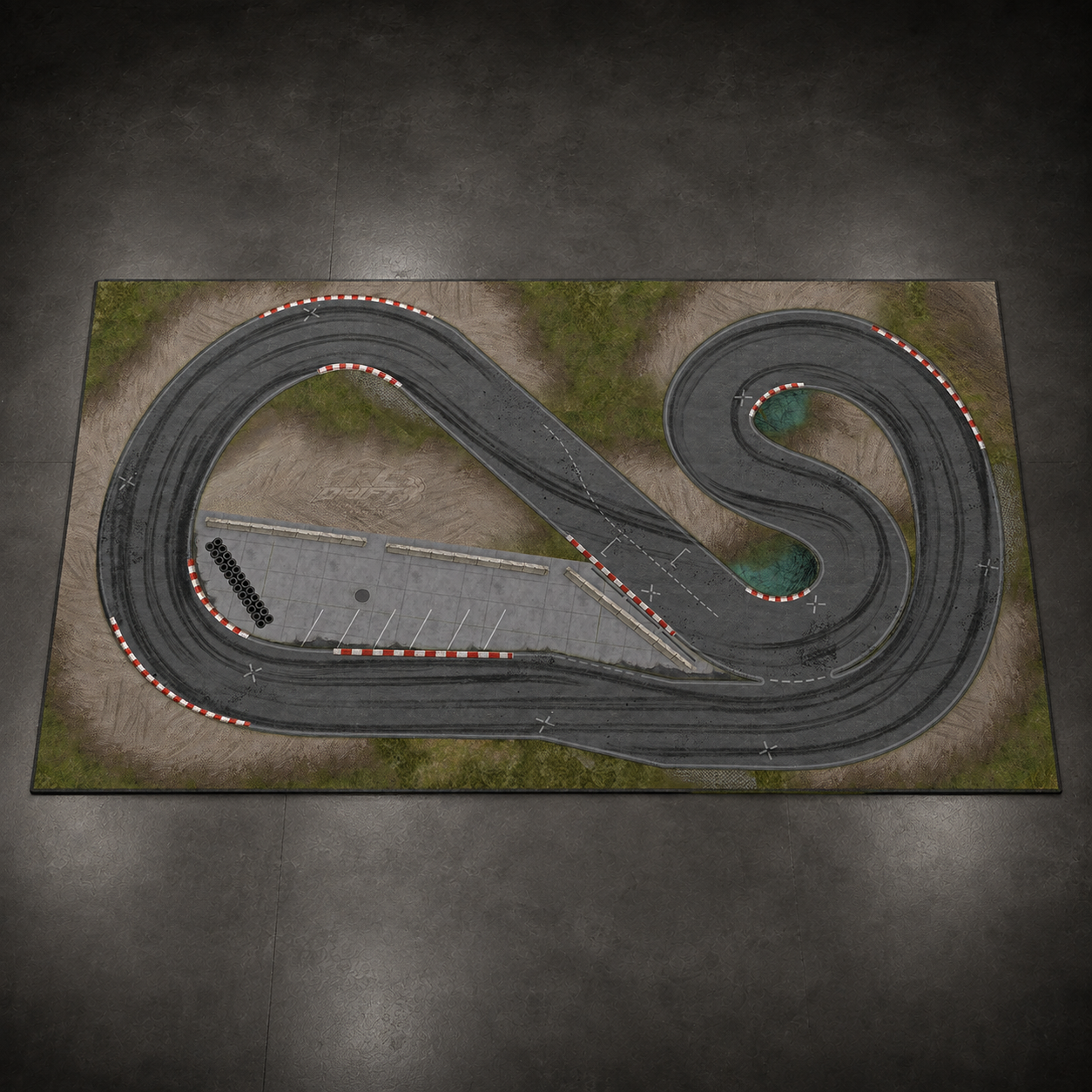
From a compact technical layout to a generous drift circuit: these current 1:24 PVC tracks give the Stage-D24 room for repeatable lines, countersteer and transitions.
Why your HPI D24 is more fun on a real drift track.
The Stage-D24 is a compact RWD drift chassis. Its steering angle and gyro help control the car, but only a defined course turns free driving into repeatable practice: corners, clipping points, transitions and lines you can approach again and again.
Fixed corner sequences let you repeat the same section and improve your line.
ROLL OUT, DON'T BUILD
No permanent model circuit: roll the track out for a session and store it afterwards.
MOTORSPORT DETAIL
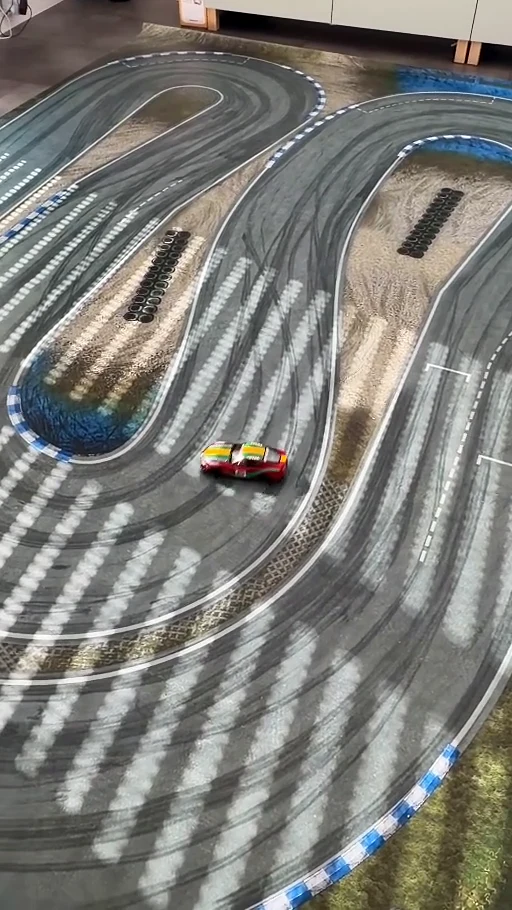
Asphalt, curbs, markings and drift traces turn the floor into a complete circuit.
SEVERAL SIZES
Choose a compact technical layout or more room for long transitions and tandems.
DEFINED SURFACE
One continuous surface makes changes to tyres and setup easier to compare.
ADJUSTABLE SLIDE
Track Reload can be used to maintain or adjust surface behaviour.
01 · SCALE VS. SPACE
183 mm Auto. Metres of drift.
At only 183 mm long, the Stage-D24 looks extremely compact. But drifting needs room for angle, countersteer, corner exit and the transition into the next bend. That is why 1:24 DriftTracks extend across several metres depending on the layout — turning a small model into a complete session with real lines.
That much countersteer deserves more than two chair legs as cones.
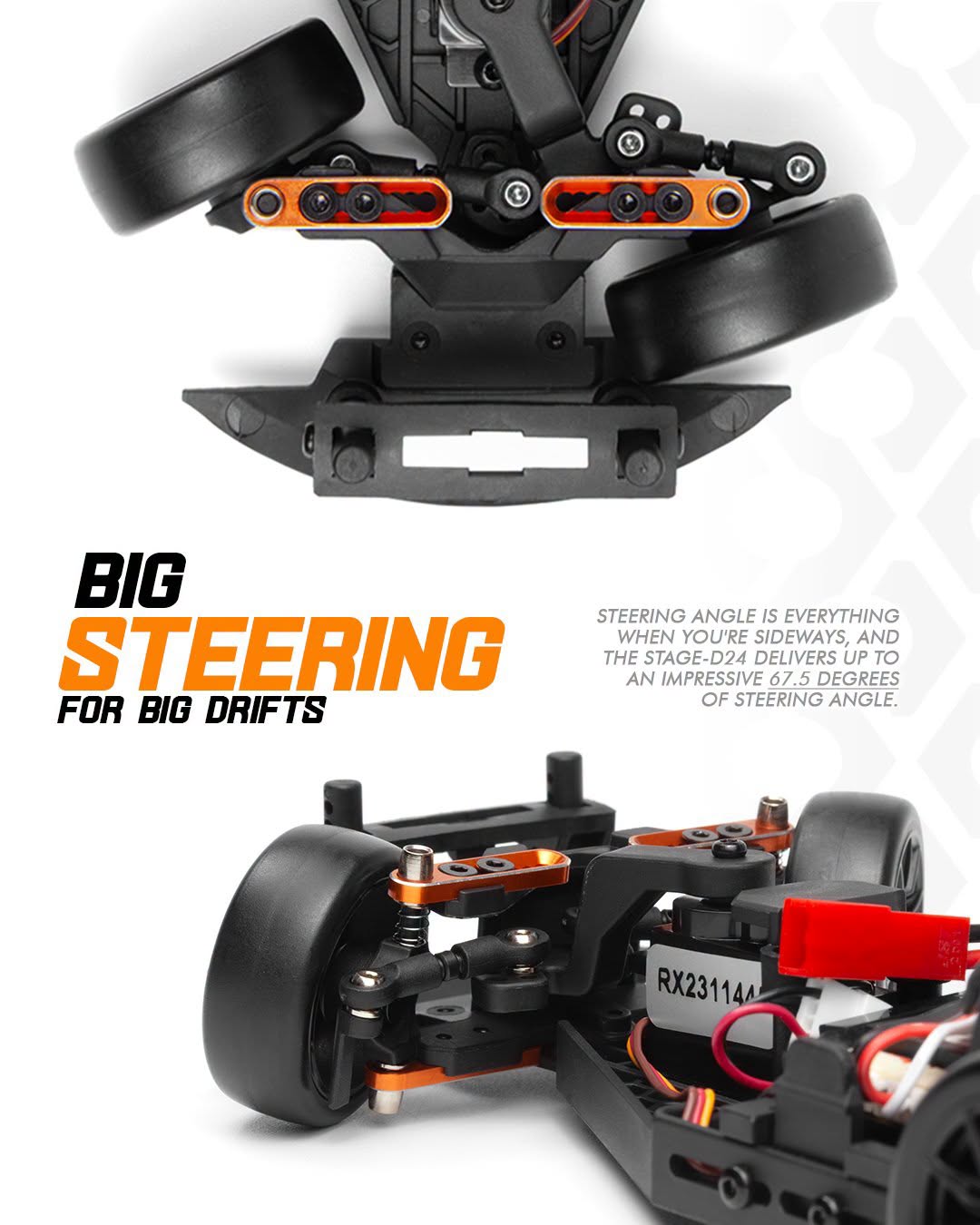
Up to 67.5 degrees of steering angle allow large drift angles and countersteer. That is exactly why the D24 needs sufficient track width and a course where the angle can be carried through the corner and into the next transition.
From the RTR box straight onto your own 1:24 drift track.
YOUR D24.
YOUR LINE.
05 · OFFICIAL HPI VIDEO
SEE WHY EVERYONE IS TALKING ABOUT IT.
Original footage. Loaded only after your click.
Official HPI Racing YouTube video. YouTube only loads after you press play.
06 · STAGE-D24 DETAILS
EXPLORE THE D24.
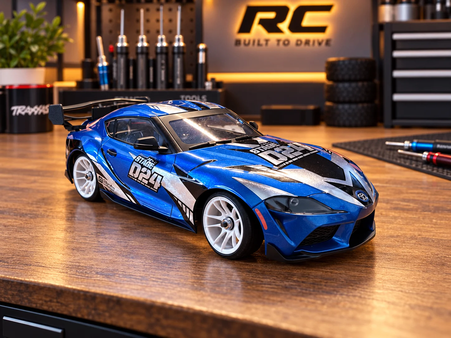
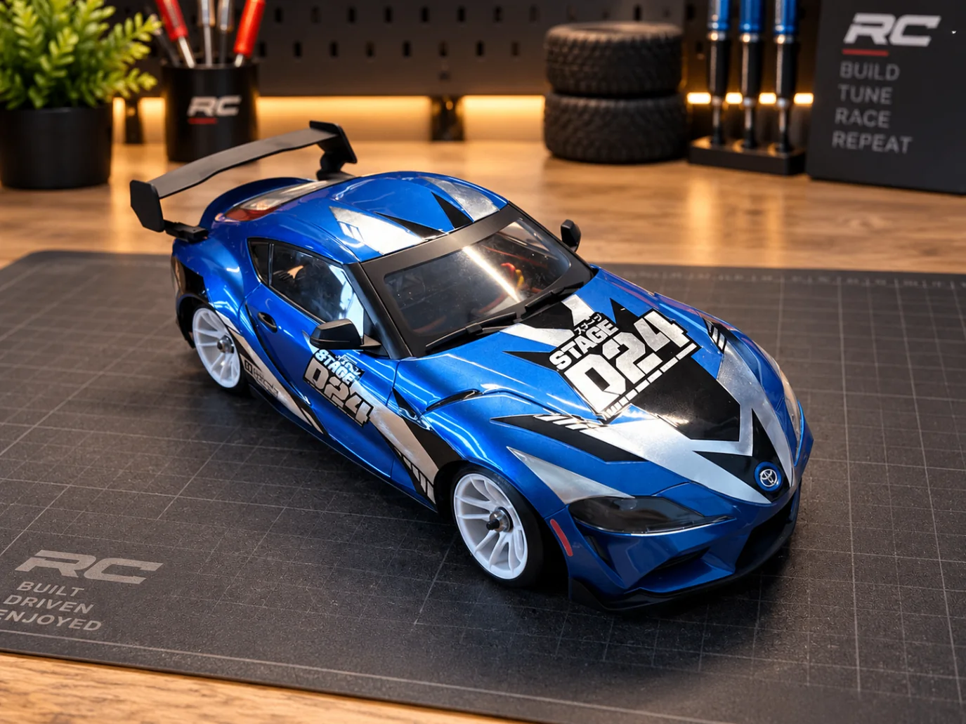
Blue HPI Stage-D24 Toyota GR Supra from the front on a wooden workbench
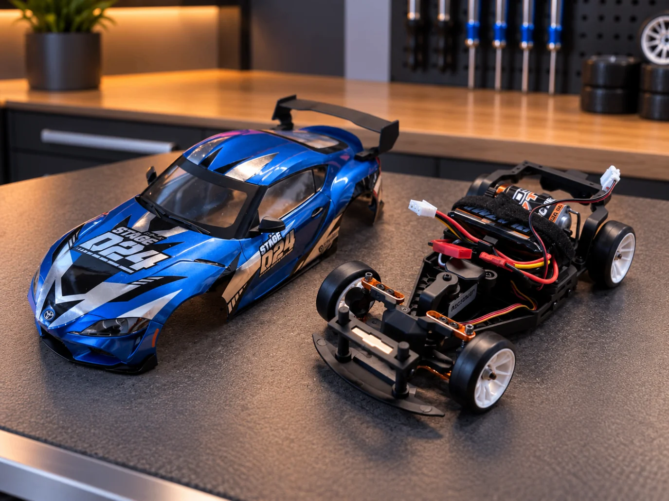
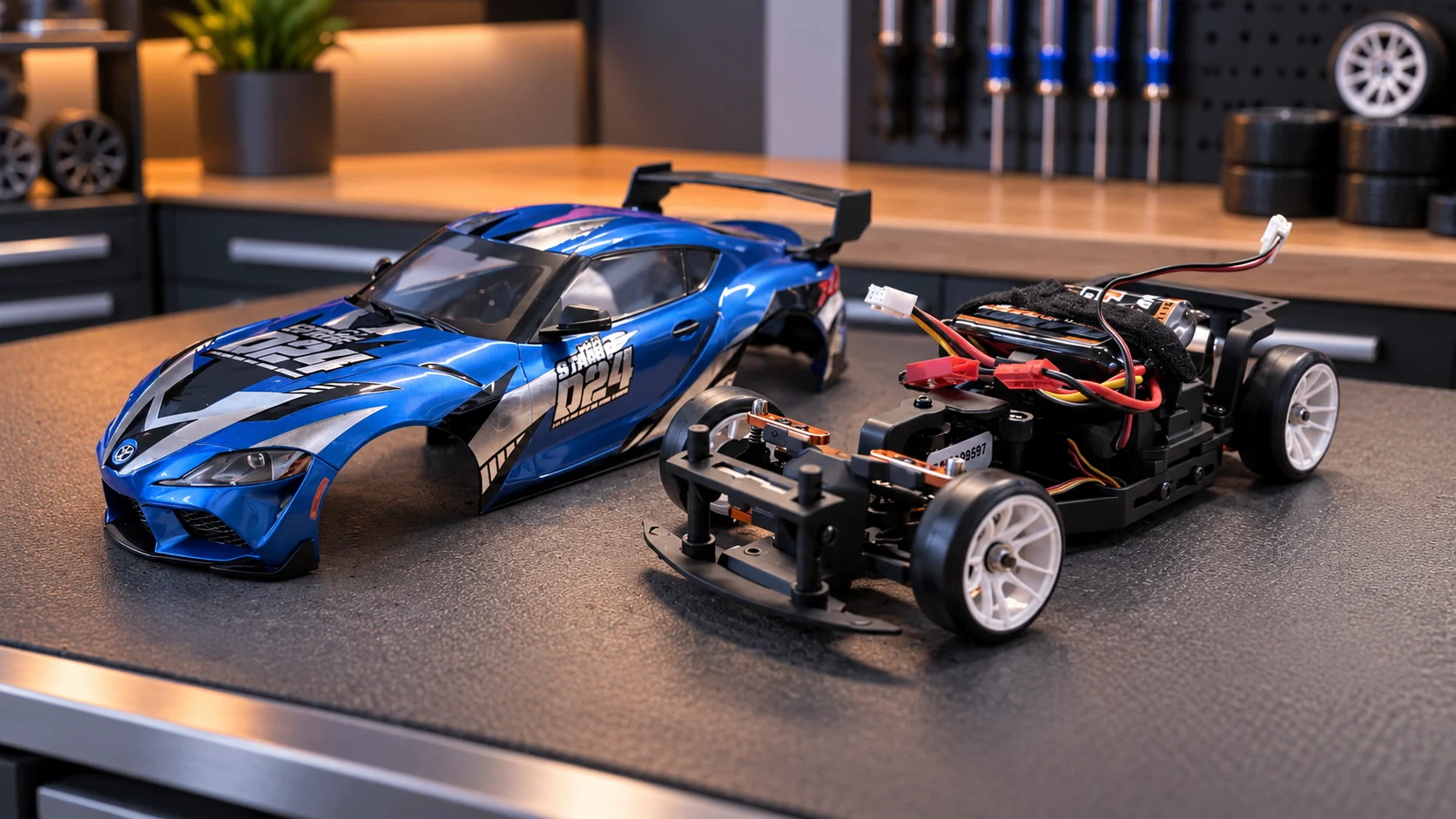
Blue HPI Stage-D24 with its body removed beside the chassis
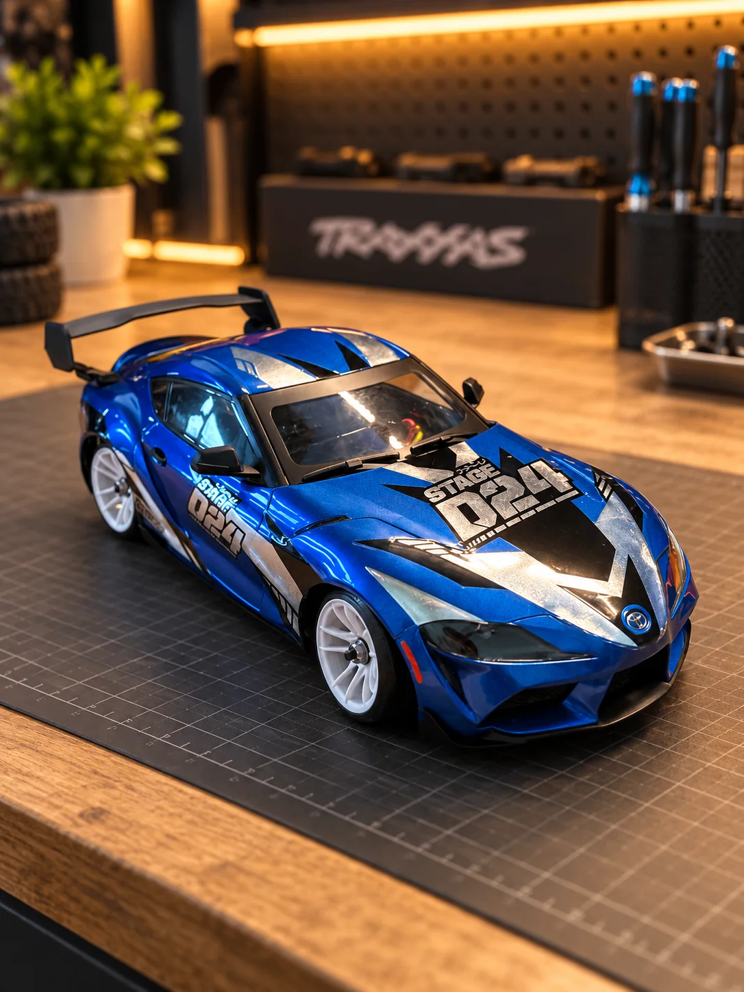
Blue HPI Stage-D24 Toyota GR Supra from the front on a cutting mat
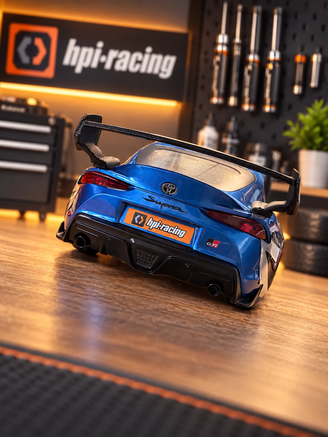
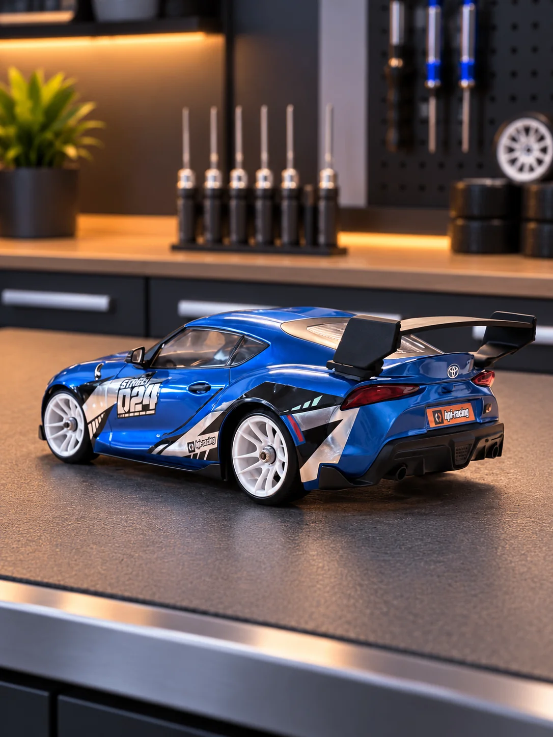
Rear view of the blue HPI Stage-D24 Toyota GR Supra
Blue HPI Stage-D24 Toyota GR Supra from the front in the workshop
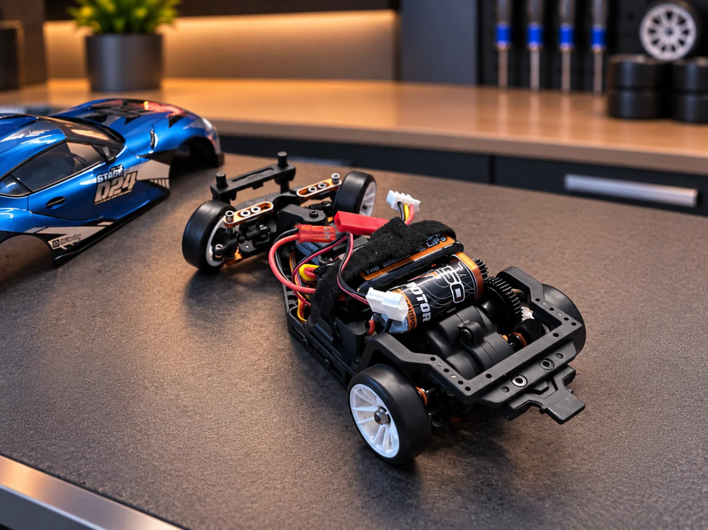
HPI Stage-D24 body and exposed chassis side by side
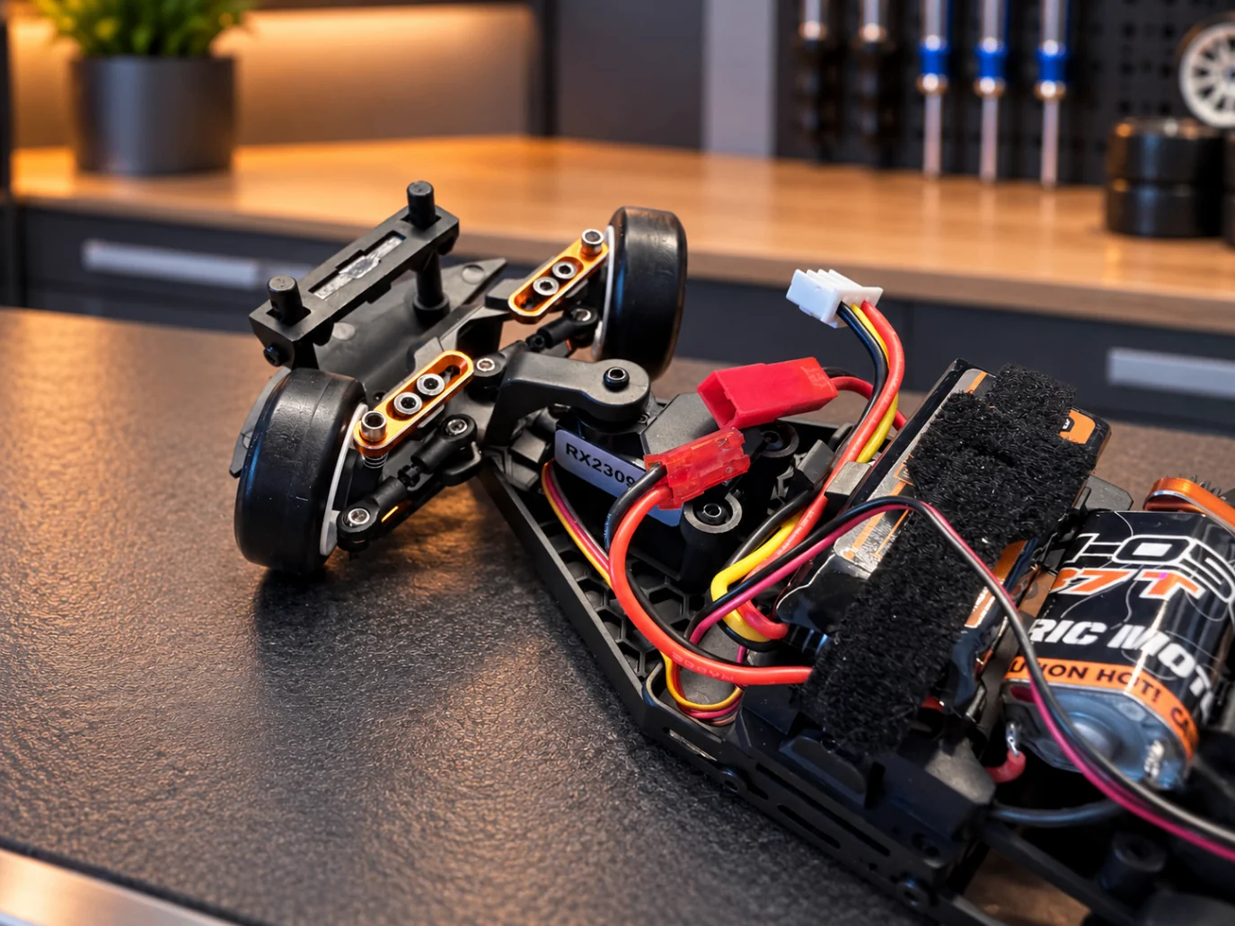
Exposed HPI Stage-D24 chassis beside the blue body
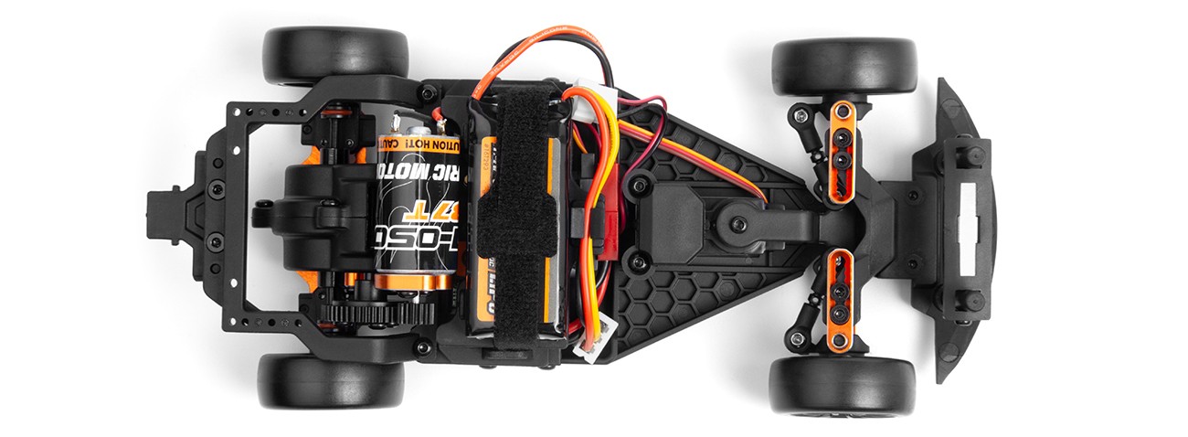
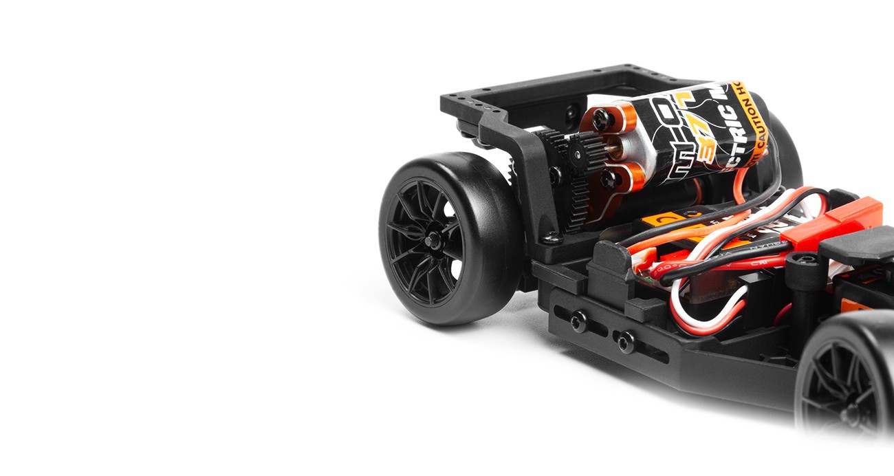
HPI Stage-D24 chassis detail showing drivetrain and wiring
Blue HPI Stage-D24 Toyota GR Supra from the rear quarter
HPI D24 showing its large steering angle
HPI Stage-D24 rear axle, motor and transmission
HPI Stage-D24 magnetic body-mount system
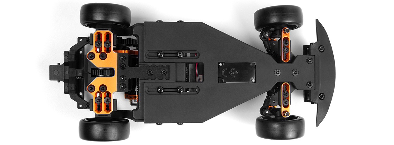
Underside of the HPI Stage-D24 chassis
SPACE & FLOW
How large should a track for the HPI D24 be?
The vehicle length alone does not determine the track size. Available room, desired speed, number of cars and whether you prefer technical or flowing lines all matter. For tandems, a larger layout usually creates more space for two vehicles to hold the same line; always plan additional clear space around the printed dimensions.
Every room and every driving style is different. Choose between technical combinations, quick transitions, tight back entries and flowing lines — always using the current images, dimensions and prices from the shop.
Set the look and your preferred driving character. The result is a non-binding track recommendation based on the three current 1:24 layouts.
Recommendation
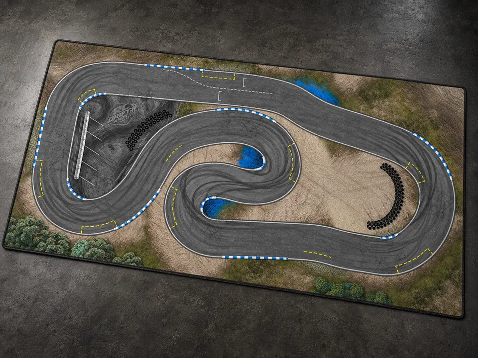
Competition Track
1:24 · 420 × 245 cm · €205.95
Planning aid only: no vehicle modification, measured braking-distance simulation or handling guarantee. Tyres, setup and surface treatment affect the result.
The best HPI D24 drift track is not defined by one universal layout. A technical course creates frequent direction changes and repeatable braking points; a flowing circuit gives the car more time to hold angle and connect transitions. Start with the usable room, then choose the character you want to practise. The recommendations above use current 1:24 products, while the general 1:24 guide explains the scale independently of a specific chassis.
Scale links the 183 mm vehicle length to lane width, corner radius and the space needed to hold a drift angle. A layout designed around 1:24 proportions gives the Stage-D24 room for countersteer and transitions without turning the course into an oversized empty floor. It remains a scale-based recommendation, not an HPI certification: tyres, gyro setting and vehicle setup determine how the car behaves on the surface.
An HPI D24 race track at home
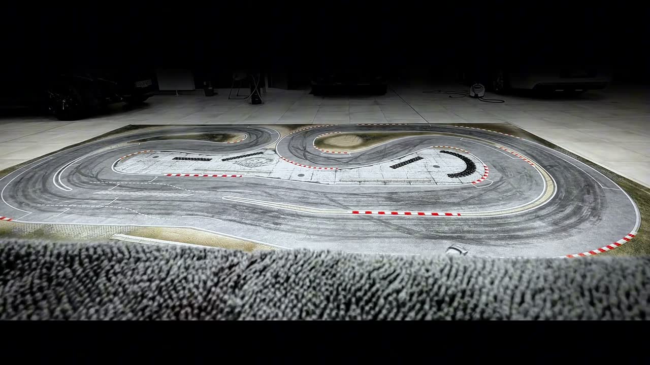
A living room, hobby room, basement or garage can become an indoor RC drift track when the printed size and additional clear space fit. The advantage of a roll-out PVC circuit is that the route, curbs and clipping points arrive as one complete layout. You do not need to build a permanent model circuit and can store the track again after the session.
Current purchasable 1:24 variants cover 250 × 150 cm – 600 × 300 cm. These are the printed track dimensions, not the complete room requirement. Add clear edge space so a drift carried too far does not end immediately at furniture or a wall, and allow access for drivers. Speed, technical or flowing lines and tandem use can make a larger layout the better choice.
PVC as a surface for RC drift
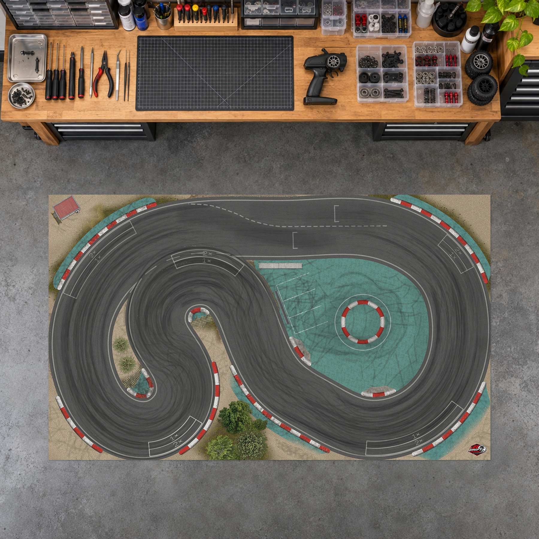
A printed PVC track provides one continuous driving surface across the complete layout. Asphalt texture, curbs, markings and drift detail can be integrated visually, while the track remains rollable for temporary indoor use and storage. Different sizes can cover compact rooms or larger sessions. DriftTracks does not claim one surface to be perfect for every setup: tyres, vehicle weight and treatment influence the actual slide.
HPI D24 drift tracks for tandem sessions
Two Stage-D24 cars can share a line when the track width, transitions and available room allow it. Larger flowing layouts generally offer more space to position a lead and chase car without removing the technical challenge. For regular tandem sessions, compare the largest current 1:24 variants first; for solo practice or smaller rooms, a compact technical layout may be the better use of space.
A PVC track is not sold as a surface perfectly tuned to every vehicle setup. Tyres, vehicle weight, setup and driving style affect handling. Track Reload can be used to maintain or adjust surface behaviour when you want to tune the slide of your DriftTrack.
The Stage-D24 arrives ready to run. The next step is the surface you want to drive on. Roll out your DriftTrack, switch on the car and approach the first line. After the session, the PVC track can be rolled up and stored again.
What is the difference between HPI 161267 and 161268?+
Both are the HPI Stage-D24 2024 Toyota GR Supra in 1:24 with rear-wheel drive. According to HPI, 161267 is Prominence Red and 161268 is Metallic Dawn Blue. The colour does not change the track choice; the same DriftTracks layouts fit both.
HPI Stage-D24 sold out – can I already plan the track?+
Yes. If your preferred model is not available at the moment, you can still plan the track by your free floor space. DriftTracks sells tracks and accessories, not HPI cars; ask your dealer about vehicle availability.
Which drift track fits the HPI Stage-D24?+
Start with a current 1:24 layout and choose it by available floor space and driving style. Drift Heaven favours flowing lines, Competition Track combines practice and tandem potential, while Back Entry Circuit has a tighter technical character. Tyres and setup still influence handling.
Which race track is suitable for the HPI D24?+
A roll-out 1:24 PVC track gives the D24 defined corners, clipping points and transitions. The printed dimensions must fit your room with additional clear space around the mat.
How large should an HPI D24 track be?+
Current purchasable 1:24 variants cover 250 × 150 cm – 600 × 300 cm. Vehicle length alone is not decisive: speed, line choice, number of cars and the available room matter too.
How much room do I need for an HPI D24 race track?+
Use the real printed dimensions as the minimum and add clear space around every side for run-off and access. The room finder compares your available area with current purchasable variants.
Can I drive the HPI Stage-D24 at home?+
Yes, in a living room, hobby room, basement or garage if the floor is level and sufficiently large. A roll-out track is useful where the circuit should not remain permanently installed.
Can I roll an HPI D24 track up again after driving?+
Yes. DriftTracks PVC tracks are designed to be rolled out for a session and stored again afterwards. Follow the care and storage information supplied with the product.
Which surface is suitable for the HPI D24?+
A continuous, defined surface helps make repeated lines and setup changes easier to compare. DriftTracks uses printed PVC; tyres, vehicle weight, setup and surface treatment still affect the slide.
Why is PVC suitable for an RC drift track?+
PVC allows a continuously printed circuit with asphalt, curbs and markings and can be rolled up for temporary indoor use. DriftTracks does not claim that one surface setting is ideal for every tyre or vehicle setup.
Are there different track layouts for the HPI D24?+
Yes. The current 1:24 range includes compact technical courses, balanced layouts and larger flowing tracks. All current purchasable layouts are listed on this page and in the 1:24 shop filter.
Can two HPI D24 cars drive on one track?+
Yes, if the chosen layout and room offer enough space. Larger tracks generally give two drivers more room to hold a shared line, but skill and speed remain important.
Which DriftTracks are suitable for tandem drifting?+
Larger, flowing 1:24 layouts create more room for transitions and two vehicles. Compare the current dimensions and choose the largest layout that fits your usable floor area.
Do the 1:24 DriftTracks only work with HPI?+
No. They are brand-open 1:24 layouts. Mentioning the HPI Stage-D24 describes a scale-based use case and does not restrict the tracks to this vehicle.
Are DriftTracks officially certified by HPI?+
No. DriftTracks is independent and does not claim official cooperation, approval or certification by HPI Racing or Toyota.
Does DriftTracks sell the HPI Stage-D24?+
No. DriftTracks sells PVC drift tracks and track accessories. Vehicle information is linked to the official HPI source; the tracks are available from DriftTracks.
Are accessories available for the DriftTracks?+
Yes. The shop includes track accessories such as Track Reload. Its purpose is to maintain or adjust surface behaviour; tyres and vehicle setup continue to affect handling.
How do I find the right track for my available space?+
Measure the clear length and width of your floor and use the room finder. It checks the real dimensions of current purchasable variants rather than relying on the vehicle scale alone.
Independent DriftTracks guide. No official cooperation, approval or certification by HPI Racing or Toyota. DriftTracks does not sell the vehicle.
Turn your HPI Stage-D24 into more than a compact RTR drifter. A roll-out 1:24 PVC track gives you defined lines, realistic motorsport detail and a complete circuit that can be stored again after the session.

 TOP PICK · 1:24